


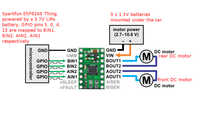

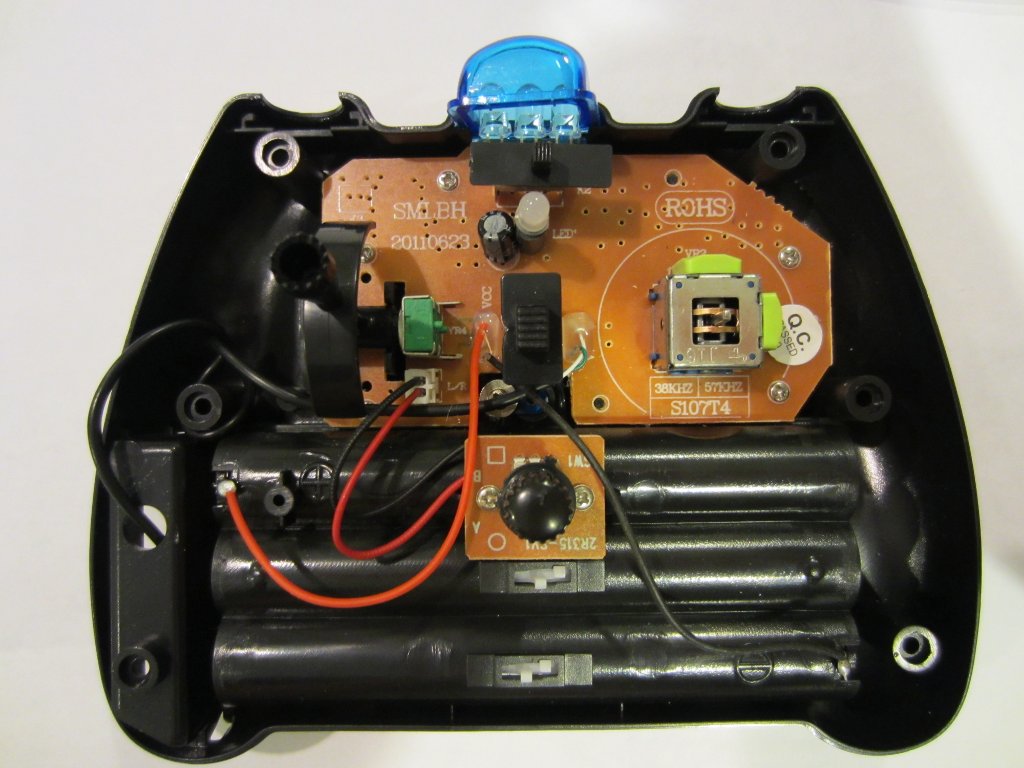


This is a second revision of 50W LM3886 power amplifier that is used to power two bookshelf speakers. The sound produced by LM3886 chip is excellent so I decided to make another amplifier with it. A remote control system for appliances makes our life smarter and easier. The wireless remote control circuit may be based on IR waves or RF waves, IR being cheaper. An IR emitter circuit is based on TSOP at the receiver section. Note that all these links are external and we cannot provide support on the circuits or offer any guarantees to their accuracy. This instructable shows how to modify an inexpensive RC car so it can be controlled by an onboard microcontroller. You can program the controller to make the car do any number of driving patterns and stunts. Receiver circuits, schematics or diagrams. com is your portal to free electronic circuits links. Copying content to your website is strickly prohibited. Automotive wiring diagrams basic symbols. Automotive electrical diagrams provide symbols that represent circuit component functions. For example, a few basic symbols common to electrical schematics are shown as: (1) Switch, (2) Battery, (3) Resistor and (4) Ground. Monostable 555 timer multivibrator circuit (one shot monostable multivibrator) is a retriggerable mono shot pulse generator. The name Mono stable indicates that it has only one stable state. Jlx Overdrive Rc Car Battery Cover Best 6 Volt Alkaline Lantern Battery Heavy Duty 12 Volt Fleet Battery Jlx Overdrive Rc Car Battery Cover 6 Volt Rechargeable Battery Charger 12 Volt Battery Cables With Connectors Taking pictures during your Disney vacation is an absolute must. Electrical motors operate on the principle that two fields within certain prescribed areas react upon each other. 16 Volt Battery For Racing Generic 12 Volt Plug In Battery Packs 16 Volt Battery For Racing Dewalt 20 Volt Max Lithium Ion Battery Little Tikes 12 Volt Battery Charger 12 Volt Batterys 1 5 Volt Battery Size Chart My real question is this: Why did he leave apparently of his car. Build a Miniature HighRate Speed Control with Brake. Many designs for highrate speed controls have been published. Most require two 8pin integrated circuits (ICs) or one 14pin IC. The first part of the project CxemCAR is here. There are also the source code for Android (Java Eclipse) and other useful information. In this article, I will describe the assembly CxemCAR for the Arduino. A phaselocked loop or phase lock loop (PLL) is a control system that generates an output signal whose phase is related to the phase of an input signal. There are several different types; the simplest is an electronic circuit consisting of a variable frequency oscillator and a phase detector in a feedback loop. The oscillator generates a periodic signal, and the phase detector compares the. This FM transmitter circuit is a quite fun project for electronics beginners, so heres a circuit with the 2SC9018 transistor. It uses the 2SC9018 high frequency transistor, based on a different spin of the common base Collpits oscillator. Learn to build electronic circuits. V Reference The circuit diagram of an Automatic Street Light Controller Circuit is explained in this post. THE POWER SUPPLY Sometimes you will see a circuit as shown in the first diagram with 12v or 12v on the top rail and 0v or a negative sign or the word negative on the bottom rail. In this case the word negative means earth or chassis of a car and we commonly refer to this as negative earth or negative chassis. In the second diagram, the output from a power supply has a positive 12. The same basic procedure is used to develop a wiring diagram from the schematic as was followed in the previous chapters. Wiring for DCC by Allan Gartner Track Wiring for Digital Command Control, Part II. We sell electronic versions of service and user manuals, part lists, schematic diagrams for home and professional audiovisual equipment, PCs and other electrical appliances..